Playing with a STANAG-4285 signal and SA (Signals Analayzer) I met some problems in understanding correctly the synchronization sequence pattern of this waveform: the solution is very simple indeed and must be sought in the way the SA phase-plane module demodulator works. Below the story.
 |
| SA phase-plane demodulating a STANAG-4285 signal |
"The synchronization phase of the STANAG-4285 waveform consists of 80 symbols and is transmitted recurrently every 106.6 ms. This sequence uses 2-bit phase shift keying (2-PSK) modulation and the modulation rate is equal to 2400 bauds. The sequence is identical to a pseudorandom sequence of length 31, which is repeated periodically within the 80-symbol window, i.e., the synchronization sequence consists of 2 periods of length 31 plus the first 18 symbols of another period. A generator for the synchronization sequence is described in pic. 1. The generator polynomial is: x^5 + x^2 +1.
At the beginning of every frame the generator is initially set to the following value: 11010. The first symbol of the synchronization sequence is identical to the least significant bit of this initial value. The remaining 79 symbols are obtained by applying the clock 79 times.
The scrambling operation is carried out on reference and data symbols only, not on the synchronization sequence."
The scrambling operation is carried out on reference and data symbols only, not on the synchronization sequence."
 |
| Fig. 1 - S-4285 sync sequence generator |
Coding PSK-2 into 8-ary on air is achieved by mapping one-bit to one-symbol according to the following rule in Fig. 2:
"000" tribit symbol for bit "0" (symbol 0)
"100" tribit symbol for bit "1" (symbol 4)
The S-4285 sync sequence generator can be synthesised running a simple Lua program: since the sync sequence is not subjected to the scrambling, the output file generated by the program is just the STANAG-4285 sync sequence that I need. The synthesised pattern of the sync sequence is visible using a bitstream analyzer (Fig. 3).
"000" tribit symbol for bit "0" (symbol 0)
"100" tribit symbol for bit "1" (symbol 4)
 |
| Fig. 2 - 0-4 mapping |
 |
| Fig. 3 - synthetized sync sequence pattern using the 0-4 mapping |
Looking at a on-air STANAG-4285 demodulated by SA phase-plane, the 80 symbols sync sequence exhibits a different pattern than the one synthesised (Fig. 4)
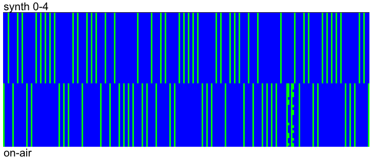 |
| Fig. 4 - synthesised 0-4 Vs on-air sync sequence patterns |
The differences with the on-air signal are more evident looking at the sync sequence generated by a STANG-4285 modem (Fig. 5)
 |
| Fig. 5 - modem Vs on-air sync sequence patterns |
while the synthesised and modem sync sequence patterns are the same, unless the polarity (Fig. 6)
Indeed, editing the mapBit() function of the Lua code adding a negative π/4 phase rotation, ie a 7-3 mapping, we get the same sync sequence pattern produced by the modem (Figs. 7,8)
 |
| Fig. 6 - synthesised 0-4 Vs modem sync sequence patterns |
Indeed, editing the mapBit() function of the Lua code adding a negative π/4 phase rotation, ie a 7-3 mapping, we get the same sync sequence pattern produced by the modem (Figs. 7,8)
local function mapBit(Ubit)
if (Ubit == "0") then
8ary_symbol = {"1","1","1"} -- # symbol number 7
else
8ary_symbol = {"0","1","1"} -- # symbol number 3
end
return 8ary_symbol
end
end
 |
| Fig. 7 - 7-3 mapping |
 |
| Fig. 8 - syntesised 7-3 Vs modem sync sequences pattern |
Editing the sync sequence generator, I found that a sequence that macthes the one of the on-air signal can be obtained by using the 4-0 mapping, ie by adding a π phase rotation as shown in Figures 9,10 (unless some uncertainties in the on-air signal):
local function mapBit(Ubit)
if (Ubit == "0") then
8ary_symbol = {"1","0","0"} -- # symbol number 4
else
8ary_symbol = {"0","0","0"} -- # symbol number 0
end
return 8ary_symbol
end
end
 |
| Fig. 9 - 4-0 mapping |
 |
| Fig. 10 - synthesised 4-0 Vs on-air sync sequence patterns |
I think that the differences between the sync sequences produced by the sythetiser and the modem and the sync sequence of the on-air signal are due to the phase-plane module of SA. SA is a signal analyzer and not a decoder, therefore its
phase-plane demodulator does not sync any particular protocol, as
it happens for example in STANAG-4285 "suited" decoders. Working with phase keyed signals, the SA phane-plane demodulator produces right interpretations and views (number of phases, angles, modulation speed, carrier frequency,...) but it may return wrong demodulated streams due to the possible phase-offset errors.
No comments:
Post a Comment