The CHX200 F1-modem (also known as CHP200 or CHP-200, i.e. the name of the embedded comunications processor) has been built in Germany by Siemens and under license in Indonesia (for domestic use). It is part of their CHX200 family of HF ECCOM frequency hopping equipment and it has been in production since 1981. Ops 1.3-30 MHz (all mode transceiver), 10 KHz-30 MHz (receive), in 100 Hz steps. Dependent on the deployment, its RF power levels range from 100 to 1000 Watts (CHX250 1000 watt station, CHX240 400 watt station, CHX210 100 watt station). Known accessories and major items include PA-400 power amplifier, ATU-400 antenna tuning unit, PA/ATU-100 power amplifier/antenna tuner, CHP-200 receiver/exciter with communications processor.
This transission consists of the selcall part followed by the non-hopping ARQ part and was heard on 10154.0 KHz, with a +1600Hz shift on USB, at 0815 UTC. The signals belong to the FSK family, the ARQ part is characterized by a costant 250 Bd manipulation speed and a shift of 170 Hz (figs. 1a, 1b).
 |
| fig. 1a - constant 250 Baud speed |
 |
| fig. 1b - ISS bursts and IRS ACKs |
The most interesting feature of this FSK signal consists in the different manipulation speeds used in the two 'segments' (here indicated as A and B) of the selcall procedure. Although the CHP200 logs (at least the ones that I found) report the 250 symbols/sec speed, a more accurate analysis of the signals shows two different speeds and this could suggest the use of the 2-way ARQ mechanism.
According to the speed measurements (and to the ARQ mechanism) it seems that the sender transmits data at 250 Baud while the acknowledgements are sent back by the receive peer at 249 Baud (fig. 2).
One could say that it's a tollerance question since the two speeds differ in only one sybol, but the difference between the segments A and B is real and is clearly shown in figure 3 (obtained after the demodulation of the signal)
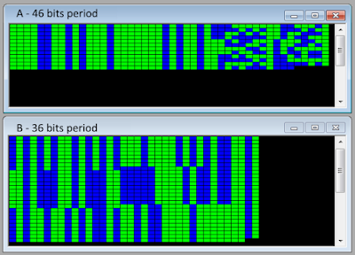
Other than the speeds, the two segments adopt different frame structures for their data transfer: 46 bits length (corresponding to a duration of 184ms) for the segment A and 36 bits length (144.5s) for the segment B, as shown in figs 4 and 5. Since these characteristics, I think that discussing about two distinct waveforms - rather than two segments of the same waveform - would be more appropriate.
 |
| fig. 5 - the 36 bit frame structure of the waveform B |
The patterns visible in the two bistreams (fig 6) resemble data + ACKs and are another clue in favor of the ARQ.
 | |
| fig. 6 |
Unfortunately I could not find official Siemens documentation about this modem and the selcall procedure: it would be interesting if someone could provide such info.
I want to thanks my friend Karapuz for pointing e in the right direction.
I want to thanks my friend Karapuz for pointing e in the right direction.


No comments:
Post a Comment